Turbinia
Private yacht
In June 1897, in celebration of Queen Victoria’s Diamond Jubilee, the Prince of Wales, foreign dignitaries and Lords of the Admiralty attended the Spithead review of the entire home fleet.
Charles Parsons, the inventor of the steam turbine, gate crashed the event as an audacious publicity stunt in his turbine driven private yacht, Turbinia. She was much faster than any other ship at the time and she raced between the two lines of navy ships. Steaming up and down in front of the crowd and princes and easily evading a navy picket boats that tried to pursue her, almost swamping them in her wake.

The Royal Navy never again commissioned a capital ship with a triple expansion engine. The age of turbine driven warships had begun.
Turbinia is preserved in Newcastle and many people have photographed her from stem to stern. You can easily find them on flickr. The model is based on the way the vessel has been preserved which appears very accurate.

Various plans are available and can be found on-line. The model is based on a combination of these, plus careful study of the museum ship
The plans I used were:
A model Shipwright plan set by Charles Sells @ 1:24 scale, the lines are based on this plan
A John Haynes plan @ 1:48 scale: contains a number inaccuracies on the lines and the deck-house locations but useful for some details
A small plan reproduced in a booklet produced by Ken Smith in 1996, reproduced below, seems to be from original drawings and so taken as very accurate, albeit small and showing the original 3 propellor set-up that was modified to 9 after severe cavitation was experienced during early sea trials

As with all plan sets drawn by others, once you get into the detail, discrepancies arise. However, the basics start with the frame centres. In Turbinia is was simple to work out that the frames are at 18 inch centres. This enables the deck houses to be positioned exactly as their ends have to rest on frames. It also positions the stanchions (also on frames) and a good guess at the longitudinal breaks in the shell plating.
After a lot of thought, as no shell expansion drawing was available, I decided to use 5 plates at the mid-ships point, giving a maximum plate width just less that 4’. As the keel strake has to be an inner, the bilge strake is an outer and the sheer strake an inner again. This seems to agree with the pictures of her in dry dock following a collision that nearly sunk her (shown below). I’m guessing that rivet lines are weaknesses and flush riveting expensive so minimising rivet lines makes sense. The shell plates all meet between frames (often forgotten that they cannot be joined on a frame line) and no two joins are in the same frame space. It may not be exactly as she was built, but it makes sense to construct it in the way. The bilge strake runs smoothly into the top of the flared stern, this can be seen clearly on one of the dry dock pictures.
The deck plating is interesting. Three strakes were used as can be seen from the pictures, with a mixture of flush and raised riveting. I’ve followed this pattern from the photographs. The raised riveting makes sense where the jolly boat is as it provides more purchase when handling the boat. I’m not sure why they went to the trouble of flush rivets elsewhere though.

This excellent picture of her in dry dock after being hit by another ship was the inspiration for the way the model is presented. Note the complex shape of the transom, designed to hold the bow down at speed
The frames were drawn on a CAD package with keel slots, printed and stuck to ply with spray mount before cutting out in 1/16th inch ply. The keel, also from 1/16” ply was held straight with 2 x ¼” timber sections. After this was sanded to the downward curve of the rear deck, the whole frame was locked together with a flat deck plate from 1/32” ply. The forward deck house was originally designed to be visible and so this section of the hull was planked. In the event, so little could be seen through the desk house windows that extra interior detail here as omitted.
Obeche blocks were cut to slide between the frames, glued and then sanded back to the ply frames. This made a very strong and straight hull with the fine stern deck slope correctly featured. The hull was then painted in a clear liquid epoxy to harden it, allowing for further shape refinement and to act as a firm base for the Aluminium hull plating.
The cambered deck was added as a superimposed additional 1/32” ply section on top of a central strip of wood sanded fore and aft to simulate the complex compound curve of the deck. The superimposed deck section contained cut-outs for the funnel and deck houses, allowing them to have flat bases.
The three propeller shaft tubes (in brass) were set into the frames before the blocks were added.
The hull plating lines were marked out on the hull, with the plate butt lines marked to ensure stagger. Each plate was then cut from Aluminium sheet (4 thou for inner strakes, 8 thou for outer) and bonded to the hull with contact adhesive. With the exception of the stern, all plates are single curvature. The stern plates were heated and beaten to shape.
The deck plates were similarly marked and cut out, however, on the deck, the frame lines had been drawn so that the rivet detail could be worked out where non-flush riveting is used. The rivets here are made with a wheel from the back of the plate, again remembering that deck plates do not join on frame lines.

The model is presented in a simulated dry-dock, with the figure of a painter just finishing up to help the viewer understand the size and scale.
The deck houses are made in wood and then plated in Aluminium with rivet detail marked out on the reverse as with the deck plating.
The wheel house is made from sheet Copper over a wooden buck, silver-soldered as are the wheel house sliding doors. The funnel is made from sheet brass (for strength) and mounted on a wooden Aluminium lined buck. I included the two smoke stacks inside the funnel casing, the boiler is double ended and I assumed two stacks were used.
The fittings are built up from custom etched parts (produced by 4D Modelshop) from my artwork.

The 9 left and right hand propellers are a key feature on the vessel. They were made by turning the hubs in brass and then silver-soldering the blades on in a jig. An etched outer ring held the blades in place, which had been turned through 45 deg for soldering, after which it was cut away and the washout refined.

The steering quadrant was built up from etched components
The window frames were soldered together over an Aluminium jig which held them centred. The Perspex glazing was then snapped in.
Using relief etching provides the opportunity for including all rivet detail, quite distinctive on some of the hatches and of course the deck-house flanges. The sheet illustrated was etched in 22 thou brass and produced ~300 pieces from an A5 sheet.
The 10’ ships boat was made with tissue paper and dilute PVA over a wooden buck containing the planking lines. This was then lined on the outside in card when dry and then fitted out in the normal manner.

Note the coffer dam sides to the tall control deck-house to prevent flooding (or try to). The boat was controlled with a large steam valve wheel located in this deckhouse
The mast and flag yard are scratch made in brass as are the other minor fittings.
I’ve fitted her with an Admiralty pattern anchor, not the Hall’s anchor she has today. This type of anchor is shown on some contemporary photographs and looked interesting to me. I’m guessing she could have carried either.

Studying the photographs, the life rings were stored on the outside of the handrails, which seems unusual practice, but is probably due to the very limited width on deck.

This shot shows how fine the hull it, really it’s just a large canoe

Showing rivet detail on the funnel. When she was running, a lookout stood on the roof of the round forward deckhouse, which would have been both exhilarating and wet.
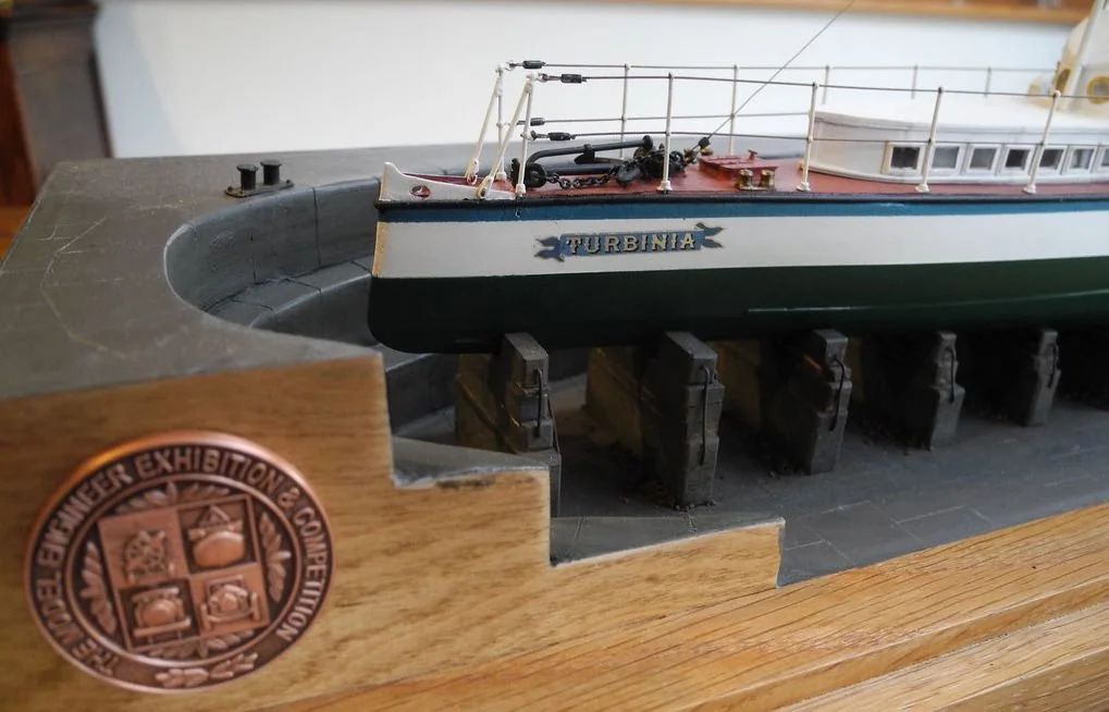
Close-up of the name badge and some of the dry-dock detailing
I entered the model into the 2014 Model Engineering Exhibition where it won a bronze metal and a cup for the best displayed ship model